BIM Viewer
Scenario: You want to import an ifc BIM graphic file and link the data to Desigo CC.
Reference: Background information is available in the information, see the reference section.
Flowchart:
Prerequisites:
- The BIM Viewer extension is installed.
- The Desigo CC project data is already imported to the Logical View.
- System Manager is in Engineering mode.
- In a BIM tool (e.g. AutoDesk Revit) the architectural information for a building and its equipment (sensor, actuators, etc.) are configured. This information is exported to one or more IFC files and available for use.
Steps:
- Select Application View.
- Select Applications > BIM graphics.
NOTE: Do not select this folder if you are updating an existing BIM graphic.
- Select the BIM Viewer tab.
- Click Edit
 .
.
- Click Import an IFC file
 .
.
- The Open dialog box displays.
- Select the BIM import file *.ifc.
- Click Open.
- After opening the IFC file (this may take some time depending on the size of the file), the content of the file is displayed as a 3D graphic and a pane opens with the hierarchy of the included BIM objects (building, flow, rooms, devices). Note that only a portion of the BIM objects are included in the IFC file.
- A Desigo CC BIM file is saved as *.ifcc in the current project, in the BIM graphic folder.
- Select Applications > BIM graphics > [graphics file].
- The file is imported and the graphic displays the building in 3D in the BIM Viewer.
- All BIM files must be imported if the BIM data is subdivided into building data and mechanical and electrical installation data (see Note below). Repeat steps 5 to 7 for each BIM file.
- Project data is not yet associated.

Lots of BIM models include more than one file, e.g. one for the architecture model and one for each of the disciplines (building automation and control equipment, safety equipment, etc.) or another partial model structure. Information on combining such partial models to create a BIM graphic is described in the following steps.
- You imported multiple BIM files to the project. You can skip this step if only one BIM file needs to be imported.
- Select Applications > BIM graphics > [building graphic].
- Click Show merged graphics list
 .
.
- The Merged BIM graphics dialog window opens.
- Select Applications > BIM graphics > [plant graphic 1].
- Drag the plant graphic to the Merged BIM graphics dialog window.
- Drag all required plant graphics the Merged BIM graphics dialog window.
- Click Close.
- Click Save
 .
.
- Automatic associations are based on the existing BIM data and engineered system data for the devices. The text must be discussed in advance with the individual parties since the texts are derived from different sources.
NOTE: BIM texts can only be supplied in one language.
- Click Toggle objects tree display
 .
.
- The BIM hierarchy structure is displayed in the BIM Viewer tab.
- In System Browser, select the Manual navigation check box.
- In System Browser, select Logical view.
- Select Logical > [Subsystem name] > [Building name].
- Drag the object folder to the BIM hierarchy structure.
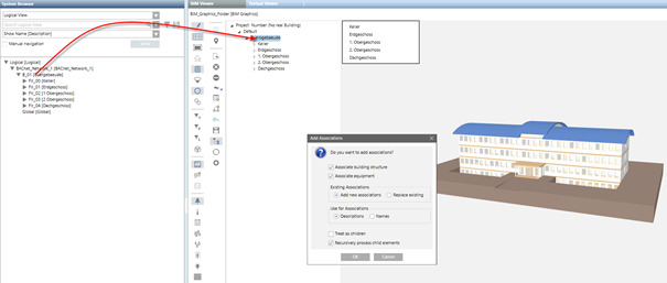
- The Add new associations dialog box opens. Details on the options are explained in the table Add options to Associations dialog box.
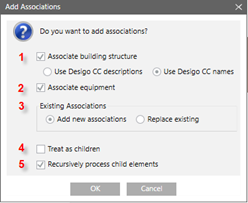
- In the Add new associations dialog box, do the following:
a. In the Existing Associations field, select either Add new associations or Replace existing.
b. In the Use for Associations field, enter Descriptions and Names.
c. Clear check box Treat as children.
d. Select check box Recursively process child elements.
- Click OK.
- The associations are created and are displayed with symbol
 and bold face text. All unassociated objects must be manually edited in the next step. No associations can be made on inconsistencies between BIM data and project data.
- Click Save .
Scenario: It is rare that all associations can be automatically generated so that the remaining objects must be manually created or edited.
- In the BIM Viewer tree, select …\Floor > Room > Object (does not yet have an association).
- In System Browser, select Logical view.
- Select Logical > [Subsystem name] > [Building name] > [Floor] > [Room] > Object.
- Drag the object to the corresponding BIM hierarchy structure.
- The Add new associations dialog box opens. Details on the options are explained in the table Add options to Associations dialog box.
- In the Add new associations dialog box, do the following:
a. In the Existing Associations field, select either Add new associations or Replace existing.
b. In the Use for associations field, enter a name and description.
c. Clear check box Treat as children.
d. Select check box Recursively process child elements.
- Click OK.
- The associations are created and are displayed with symbol and bold face text.
- Click Save .
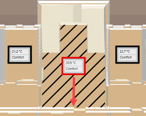
Scenario: The room value display is placed in the middle of the given room by default. The room value display can be manually moved to another position if the position is unfavorable.
- Select Applications > BIM graphics > [building graphic].
- Click Show floor list
 .
.
- The flow list is displayed in the top left-hand corner of the graphic page.
- In the floor list, click the desired floor.
- The floor plan is displayed.
- Highlight the room value display (highlighted in red) and move it to the new position.
- The changed position remains if the BIM data is reimported. Editing may be necessary is rooms are merged or walls are moved during an update of BIM data.
- Click Save .