Additional Procedures
Prerequisites:
- The Edit mode
 is selected in the BIM viewer.
- Select Application View.
- Select Applications > BIM Graphics > [graphics page].
NOTE: Do not select folder Applications > BIM Graphics in this case. Any associations and changes in position are lost if the same BIM file is imported on this folder level.
- Select the BIM Viewer tab.
- Click Import an IFC file
 .
.
- The Open dialog box displays.
- Select the desired *.ifc BIM import file.
NOTE: No plausibility check is made for correct import data.
- Click Open.
- The graphic page is overwritten.
- Select Applications > BIM graphics > [graphics file].
- The file is imported and the graphic displays the building in 3D in the BIM Viewer.
- All BIM files must be imported is the BIM data is subdivided into building data and mechanical and electrical installation data. Repeat steps 4 to 6 for each BIM file.
- Existing association to project data is retained.
- Click Refresh associations
 .
.
- Refreshes the associations for all the project data. This function overwrites any unsaved associations.
- Select the appropriate level in the BIM hierarchy structure.
- Click Remove Associations
 .
.
- Displays Remove Associations dialog box displays.
- In the Remove Associations dialog box, do the following:
a. Select the Remove distinct associations check box.
b. Select check box Recursively process child elements.
- Click OK.
- All associations as of the selected BIM hierarchy structure are removed.
- Select the appropriated BIM graphic.
NOTE: All assignments and changed positions are lost once the BIM file is deleted
- Click Delete BIM Graphic
 .
.
- A confirmation dialog box opens.
- Click OK.
- The current BIM graphic is deleted.
Scenario: You want to display a customized initial view when operating the BIM viewer since it differs from the default version.
- Add the overview graphic on the graphic page.
- Determine the view angle and graphic size.
- Click Set current camera view as initial view
 and select Set initial view for building.
- A confirmation dialog box opens.
- Click OK.
- Click Save
 .
.
- The view is saved and the new position is displayed the next time you select Overview
 .
.
Scenario: You want to display a customized initial view when opening a room since it differs from the default version. You can do this for each room.
- Open a room in the BIM graphic.
- Determine the view angle and graphic size.
- Click Set current camera view as initial view and select Set initial view for room.
- A confirmation dialog box opens.
- Click OK.
- Click Save .
- The view is saved and displayed as the new start position the next time the room is selected.
Scenario: You have is one large room in the BIM data. But for control technology reasons two or more system data rooms must be added to this room. In the case, additional system data rooms must be manually assigned to the BIM data room.
- Click Toggle objects tree display
 .
.
- The BIM hierarchy structure is displayed in the BIM Viewer tab.
- In System Browser, select the Manual navigation check box.
- In System Browser, select Logical view.
- Select Logical > [Subsystem name] > [Building name] > [Floor] > [Room] > > [Room 118] > {RHavcCoo} HVAC room coordination.
- Drag the RHavcCoo object to the corresponding room 117 in the BIM hierarchy tree.
- Select Applications > BIM graphics > [building graphic].
- Click Show floor list
 .
.
- In the floor list, click the desired floor.
- Two or more room value displays are available in the BIM room.
- Highlight the room value display (highlighted in red) and move it to the new position.
- The changed position remains if the BIM data is reimported. Editing may be necessary if rooms are merged or walls are moved during an update of BIM data.
- Click Save .

Scenario: BIM data describes every detail of a building. This does not always make sense for operation since it can impact the overview for navigation. As a consequence, Desigo CC provides various types of filters. The user can, however, only apply Filter 1 and Filter 2 for operation.
| Select option for filter response |
L |
|
H | Objects are always hidden when applying the first filter. Additional filters have no influence on the visibility of the objects. |
S | Objects are always shown when applying the first filter. Additional filters have no influence on the visibility of the objects. |
Define Load Filter L
Scenario: Unneeded objects can be hidden in order to accelarate the loading of a BIM graphic. The load filter acts on all object of the same type in the graphic.
- BIM data configurations are undertaken.
- Click Loading filter
 .
.
- The Filter L dialog window opens.
- In column H, the select the object types to be hidden in the graphic. Hidden objects can be shown again when applying additional filters.
- Click Set.
- Click Save .
Individual Filter
Scenario: You only want to hide a few objects on your graphic. The individual filter can highlight objects directly in the graphic and select the following options:
- Hide this element
- Hide this part of the element
- Hide all elements of this family
- Hide this part of all elements of this family
- Hide all elements of this IFC type
- Hide element
- Select an object in the graphic.
- Click SHIFT + Right-click.
- Select from one of the displayed options.
- The object or object group is immediately hidden.
- (Optional) If you selected the incorrect object, click Undo last hide action
 .
.
- Click Save .
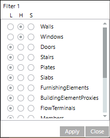
Define Visibility Filter 1 and 2
Scenario: You want to influence visibility during graphic operation. Filter 1 and Filter 2 can be applied individually in operating mode or as an AND filter.
- Click Filter 1
 .
.
- The Filter 1 dialog window opens.
- Select in the column:
- H for object types to be always hidden in the graphic;
- S for object types to be always shown in the graphic.
- Click Set.
- Click Save .
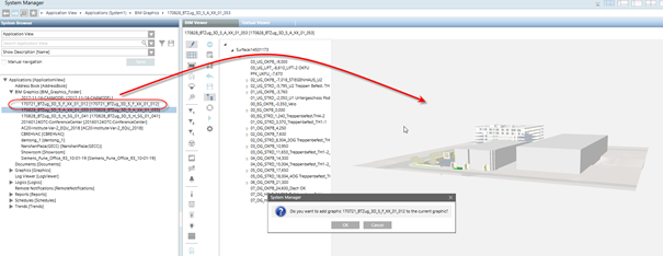
It is possible to combine several BIM graphics. This is useful if you have multiple IFC files for one BIM project, for example, one for the architectural model, and one for each discipline (building automation equipment, electrical equipment, security equipment etc.).

Note that the coordinate systems of the different IFC graphics must be synchronized. It is not possible to move combined files.
Base workflow (for details, see step-by-step workflow):
- Create a separate BIM graphic for every IFC file and save it as a normal BIM graphic.
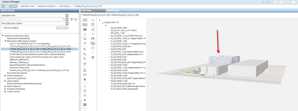
- Open the base BIM graphic in the BIM Viewer (usually this is the architectural model, but this is not mandatory) and drag the graphic(s) to be merged (usually the models with equipment) from the Application View to the BIM Viewer window.
Example of the combination process
The base BIM graphic
The additional BIM graphic (here, the windows)
Dragging the additional graphic onto the base graphic
The result
When saving the base BIM graphic, the information about the combined graphic(s) is also saved. Upon opening the base BIM graphic again, the additional graphic(s) are loaded automatically.
- When selecting the base BIM graphic in the System Browse the full combined graphic will display. Selecting another (part) graphic will only display this graphic on its own.
- Recursive combining is not supported, e.g. if the additional BIM graphic contains combined graphics itself, the result will not be as desired.
- Click Generate floor plan(s)
 .
.
- A confirmation dialog box opens.
- Click OK.
- All floor plans are generated and updated.

Note:
Any generated 2D graphics (only those generated from BIM data) must be generated again if the BIM data is reimported.